High-accuracy 16 bit DAC for Arduino
Below you will find the source code I've used to test the DAC board.
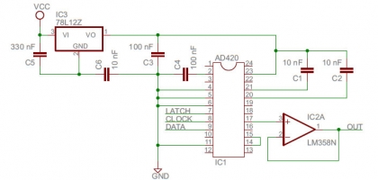
The schematic also includes a voltage regulator, in the current prototype I'm not using it but if you want to use a power supply greather than 14V i would suggest it (otherwise just remove IC3, C5 and C6 from the schematic).
	/*---------------------------------------------------------*/

	/*   AD420 Serial Input 16bit DAC example                  */

	/*   Vincenzo Pacella - www.shaduzlabs.com                 */

	/*---------------------------------------------------------*/


	//arduino output pins

	#define LATCH 7

	#define CLOCK 8

	#define DATA  9


	//2 uS of clock period (sample rate = 30.3 KHz)

	#define HALF_CLOCK_PERIOD 1


	uint16_t j=0;


	void setup()

	{

	  pinMode(DATA, OUTPUT);

	  pinMode(CLOCK,OUTPUT);

	  pinMode(LATCH,OUTPUT);


	  digitalWrite(DATA,LOW);

	  digitalWrite(CLOCK,LOW);

	  digitalWrite(LATCH,LOW);

	}


	void writeValue(uint16_t value){


	  //start of sequence

	  digitalWrite(LATCH,LOW);

	  digitalWrite(CLOCK,LOW);


	  //send the 16 bit sample data

	  for(int i=15;i>=0;i--){

	    digitalWrite(DATA,((value&(1<<i)))>>i);

	    delayMicroseconds(HALF_CLOCK_PERIOD);

	    digitalWrite(CLOCK,HIGH);

	    delayMicroseconds(HALF_CLOCK_PERIOD);

	    digitalWrite(CLOCK,LOW);

	  }


	  //latch enable, DAC output is set

	  digitalWrite(DATA,LOW);

	  digitalWrite(CLOCK,LOW);

	  digitalWrite(LATCH,HIGH);

	  delayMicroseconds(HALF_CLOCK_PERIOD);

	  digitalWrite(LATCH,LOW);


	}


	void loop()

	{

	  //a 0 to 5V triangular waveform

	  for(j=0;j<65535;j+=5){

	    writeValue(j);

	  }

	  for(j=0;j<65535;j+=5){

	    writeValue(65535-j);

	  }


	}
